

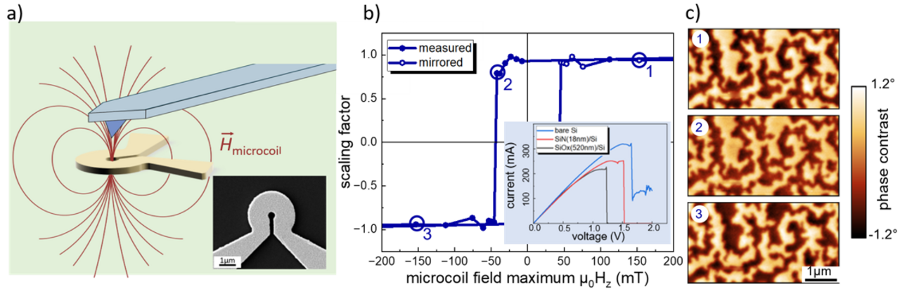
Magnetic force microscopy (MFM) is nowadays a powerful standard technique for investigating nanoscale magnetic textures. It relies on a magnetic probe – a tip attached to a cantilever – in a well-defined magnetic state, typically magnetized along the tip axis. Despite its fascinating capabilities, MFM contrast contains artefacts from non-magnetic tip-sample interactions (topography, electrostatic charges, surface potential differences), which can be most effectively subtracted by measuring the sample with two opposite tip magnetization states. To ease this measurement procedure, we develop micrometer-sized coils, with the aim of repeatedly switching the magnetization state of the MFM tips. Being currently structured on flat Si substrates, coils with an inner diameter of 1 µm do allow repeated ms-long, quasistatic current pulses up to 300 mA (see inset of Fig. b), which produce a peak field in the coil center of above 150 mT.
Within a DFG project we team up with our colleagues from the Institute for Solid State Research at IFW-Dresden to optimize coils for appropriate field profiles [1, 2], and analyze the switching behavior of MFM tips by performing series of zero-field MFM measurements, with the tip being exposed to various micro-coil fields. The contrast scaling factor evaluated from these images (Fig. c) allows to construct the tip reversal hysteresis (Fig. b) and confirms that micro-coil fields are sufficiently large to obtain a full contrast inversion on a TbFe-reference sample.
The objective of our project is to foster the small size, the large stray fields (> 150 mT) and the large field gradients (> 0.5 T/µm) of these micro-coils to implement an integrated differential MFM imaging mode by directly structuring micro-coils on a cantilever.
[1] Patent pending DE 10 2023 135 257.1
[2] A. Sathyadharma Prasad, R. Ravishankar, B. Büchner, V. Neu, T. Mühl, Communications Materials 6, 164 (2025)
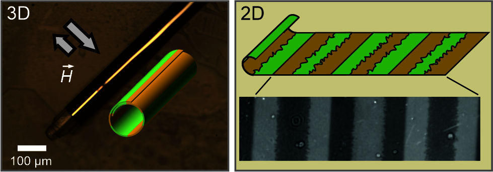
Controlling the domain arrangement and tailoring the magnetic moment configuration at the domain boundaries is essential for the performance in various application. Specifically tailored magnetic domains and their associated magnetic stray field landscapes allow particle guidance in Lab-on-Chip magnetophoretic applications [1,2] and the tailoring of broad band microwave components [3], domain boundaries can serve as wave guides in magnonic applications [4], and magnetic textures can even be imprinted into other material systems [5]. In a new approach, we utilize a self-assembled rolling of a polymer carrier membrane to transform a magnetic layer into a multiwinding tubular structure. When polarizing the rolled-up 3D structure in a simple homogeneous magnetic field, the imprinted configuration translates into a regularly arranged multidomain configuration once the tubular structure is un-wound.
In this IFW excellence project the “Magnetic Microscopy and Thin Film Devices” group teams up with the Department for “Chemistry of Functional Materials” of IFW to explore the effect of stray field landscapes for a structured deposition via a magnetoelectrodeposition process, making use of the additional magnetic gradient forces acting on the paramagnetic ions in the electrolyte. We study this effect starting from sub-millimeter-sized stray field landscapes and successively reduce the dimensions of the underlying magnetic domain pattern.
[1] B. Lim et al., Nat. Commun. 5, 3846 (2014).
[2] A. Sarella et al., Adv. Mater. 26, 2384 (2014).
[3] H. Wu et al., IEEE Trans. Magn. 48, 4123 (2012).
[4] K. Wagner et al., Nat. Nanotechnol. 11, 432 (2016).
[5] Z. Yang et al., Nat. Commun. 8, 1564 (2017).
See: K. Tschulik et al., Electrochim. Acta 56, 5174 (2011). V. Neu et al., Nano Letters 21, 9889 (2021).


